DZR
Well travelled
- Location
- France Billere
I am preparing the 2018's Himalayan of my daughter (silk road project 2022).
1 What type of long life battery advised to replace Royal Enfield part?
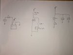
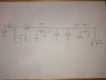
2 I am going to install a double USB socket (2*2A), a handlebar GPS and fog lights (Halogen). All the 3 devices to be connected to the battery output.
To help, I am loocking for a simple electric diagram and also ideally a tutorial (video).
Thanks in advance for help
DZR from Billere France
1 What type of long life battery advised to replace Royal Enfield part?
2 I am going to install a double USB socket (2*2A), a handlebar GPS and fog lights (Halogen). All the 3 devices to be connected to the battery output.
To help, I am loocking for a simple electric diagram and also ideally a tutorial (video).
Thanks in advance for help
DZR from Billere France